


Introduction to back-propping
Introduction to back-propping – what is it?
Back-propping of RC slabs during construction is often neglected or misunderstood in the civil engineering industry. Regrettably, many permanent works designers still consider the subject as not relevant and a contractor’s issue.
This article puts some light on the theory and background to back-propping and gives advice on the methods recommended for back-propping calculations. It explains the physics involved and how engineers and designers can avoid or prevent damage to concrete slabs during construction.
The issue is really quite simple: almost every new building is designed for imposed loads which are only a small part of the total design load. In many commercial buildings the sum of design live loads and superimposed dead load is only 40% of the self-weight of the concrete floor, and in apartment buildings often less at 25%. Therefore, the self-weight of the newly cast slab cannot be taken by the recently completed slab below (often an oversight of permanent works engineers when designing low capacity suspended ground floor slab which cannot be back-propped), and the construction loads need to be distributed to lower floor slabs. This transfer of load through the structure is known as “back-propping”.
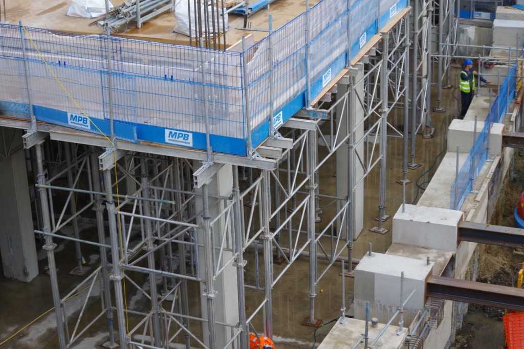
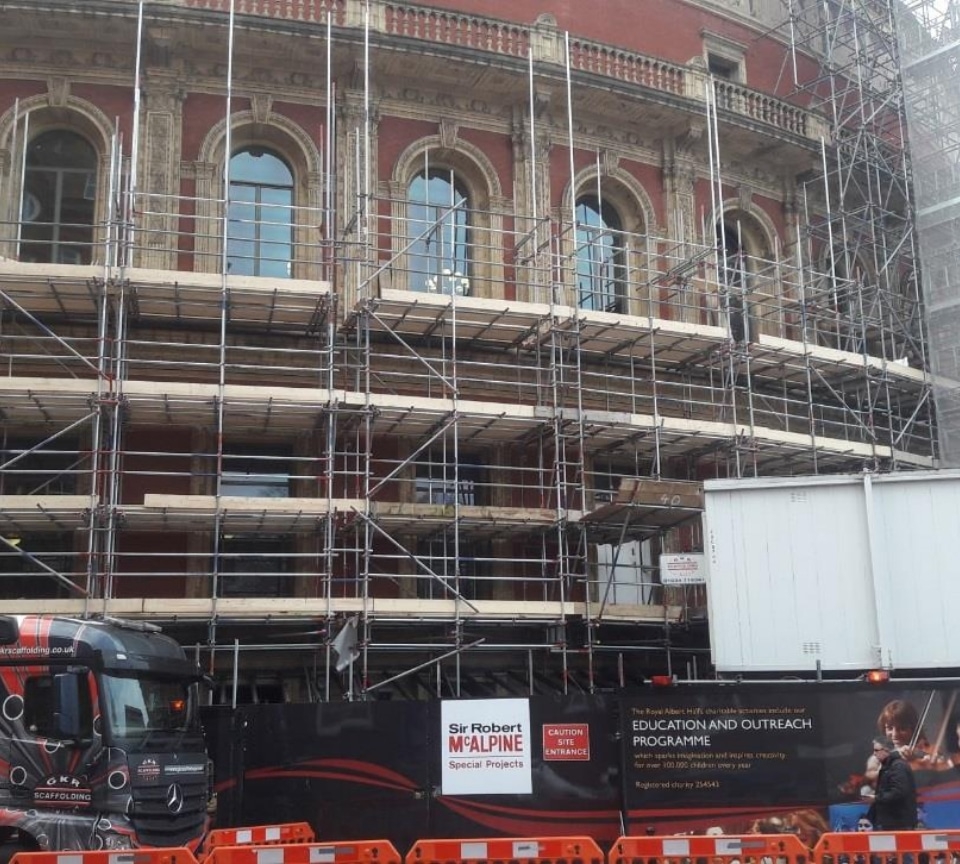
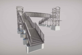
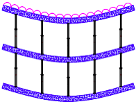
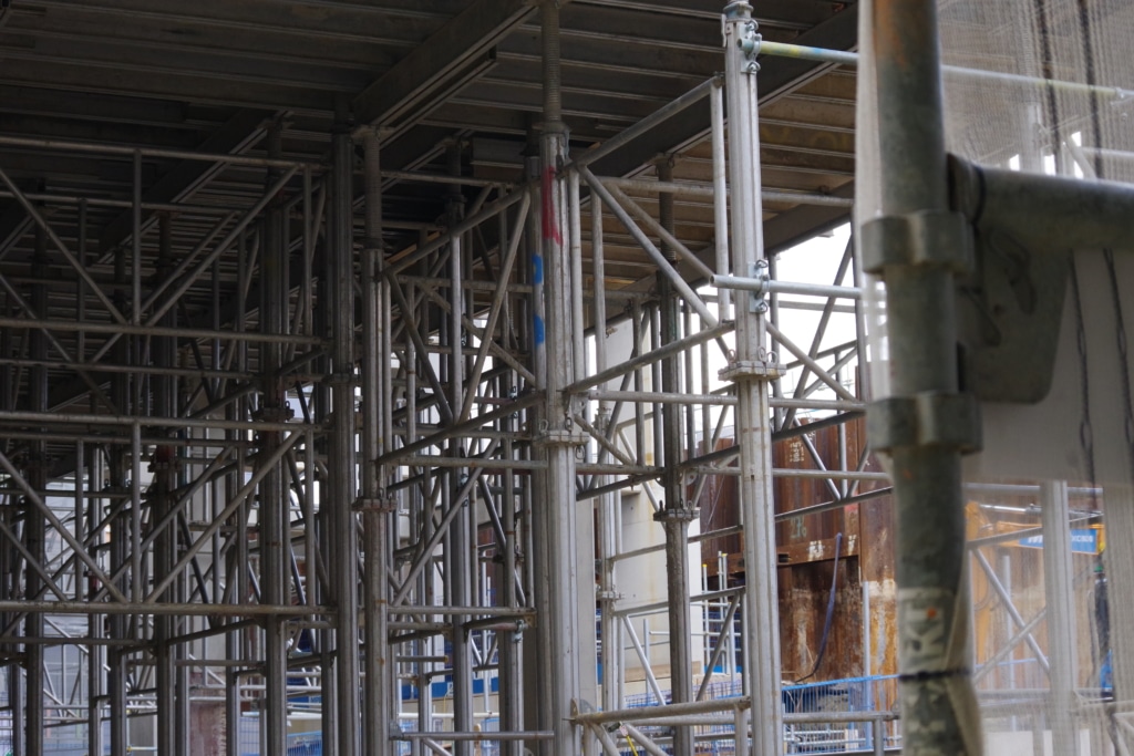
(Figure 1. Properly designed back-propping)
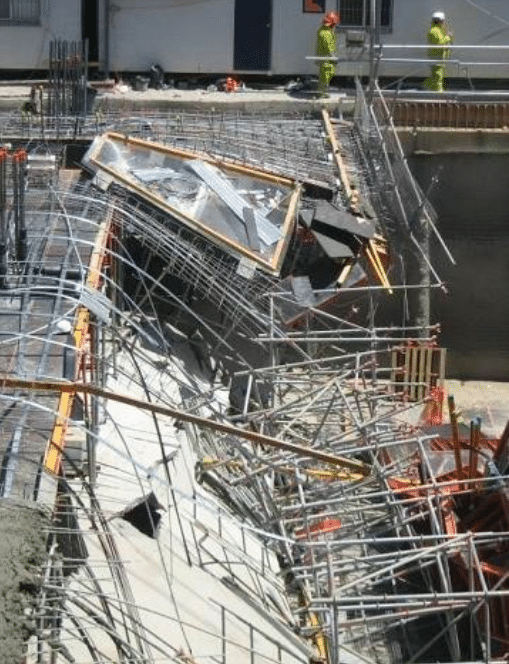
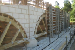
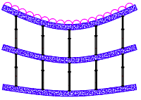
(Figure 2. What can happen if the subject is neglected)
The Physics – How it Works
The mechanics of how load is transferred through slabs is basic physics: the deflection of a slab is proportional to the total applied load on the slab – it needs to deflect in order to carry the load.
If you have three identical floor slabs separated by rigid props (Figure 3), applying a load to the top slab would cause all three slabs to deflect by the exact same amount. Therefore, each slab would effectively be taking 33% of the total applied load, as load/deflection is proportional.
In reality however this is not correct, because the props are non-rigid members. If you have the same three identical floor slabs, but now separated by elastic props (Figure 4.), as the load is applied to the top slab, the props have to physically shorten in order to transfer load to the middle slab and then to the bottom one. The uppermost slab must now deflect more than the middle slab, which will deflect more that the bottom slab. Thus, distribution of load will not be even. The theory predicts an approximate 65:23:12% load split (70:30% for situations with only two slabs).
The simple example does not take account of many other physical aspects, such as different stiffnesses of the constructed floors (newer floors are less stiff than older floors and hence have different deflection properties), different stiffness of the back-props (steel back-props will transfer bigger part of total load compared to the aluminium ones), amount of pre-load force in back-props (which will certainly occur, but is very difficult to measure and control) and finally all effects relating to shrinkage, creep and temperature changes.
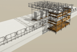
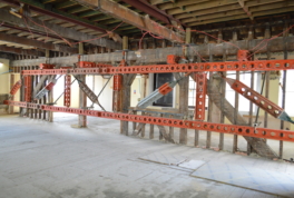
(Figure 3. Rigid props)
(Figure 4. Elastic props)
Methodology – How To Approach It
The most important aspect in back-propping design is to understand how much load is being transferred and to where. If you leave propping under a slab that has just been cast, such as installing “re-props” while striking the falsework to that slab, a designer has no idea where the weight of the slab and any imposed load is being supported. It is therefore an important rule of thumb in back- propping calculations that the formwork/falsework to a recently cast slab be struck completely. The new slab is allowed to take up its instantaneous deflected shape under self-weight, and only can a designer confidently assume that the floor self-weight is now being transferred directly to the permanent supports of the columns/walls, etc.
The other question is how to model the structure in the temporary condition. When a new concrete floor slab is poured is it acting as a uniformly distributed load or maybe as a series of point loads? Can the back-propping grid be assumed to act as a planar spring support or does it cause additional bending moments and shear forces in concrete slab similar to concentrated loads?
Thinking in three dimensions complicates back-propping calculations still further. It is more usual for designers to simplify the approach and regard the applied loads from the formwork/falsework as a distributed load applied to the supporting slab.
There are four methods by which designers can complete back-propping calculations, which are as follows.
Method One
The use of fixed percentage values shown in Figure 5. is the most common method of predicting the loads transferred through slabs. It is based on the University of Leeds research and was also reproduced in Clause 19.3.4 of BS 5975. The biggest advantage but also disadvantage of this approach is its simplicity. The calculations can be done in a couple of minutes on however it is important not to forget the limitations of this method. Basically, those stated load split proportions were determined for specic conditions.
It is assumed that all floors are suspended slabs and have the same thickness (which shouldn’t be larger than 350mm). Also, that the back-props are arranged on much larger grid than falsework (typically at 1/3rd points of spans). As conditions on each construction site are different, it is generally recommended that more complex analysis is adopted in assessing the back-propping requirements.
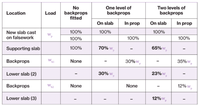
(Figure 5. Percentage of load distribution in method one)
Method Two
This method uses the equations established by the University of Leeds (Figure 5.) to predict the load transfer, knowing the relative stiffnesses of the slabs and back-props. The analysis assumes that the structure is in two dimensions only, but still covers more design situations than method one. Using these equations it is possible to consider different thicknesses and even different curing times of supporting slabs. Also, it can be used where the back-propping is taken direct to the rigid foundation by substituting infinity as stiffness of the bottom slab.
In addition to the above points this method allows the prediction of the load distribution in different arrangements of back-props. In many scenarios the falsework is left in place after it is struck, to act as back-propping to the next level. It is natural that in “leg for leg” configurations the stiffness of back-propping is much higher and therefore the load split is more even – closer to the theoretical 50/50% or 33/33/33%.
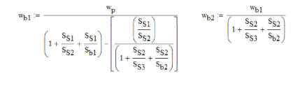
(Figure 6. Equations to determine percentage of load taken by back-propping)
Method Three
This method is just a further simplication of equations from method 2. It assumes that the RC slabs will be at least twice the stiffness of any back-propping introduced. It can be used in initial calculations for assessing the amount of back-propping required or for checking slab capacities.
Method Four
This method is the most complex by using a three-dimensional model of the structure. It introduces deflection coefficients and allows for the location of the slab and exact positions of falsework and back-propping grids. The calculation is presented as an Excel spreadsheet attached to CS140: Guide to at slab formwork and falsework (CSG, 2003).
Method Five
Where slabs of varying stiffness, downstand beams, irregular column grids or irregular propping grids are adopted, then finite element modelling gives a more precise distribution of forces and deflection.

Read more of our Technical Guidance.