


Façade Retention Design
Civil and Structural Engineering | 3D Modelling & BIM
IDH Housing Design | Training
Façade retention structures are increasingly common, and in many cases necessary to commence construction or reparation works.
There are several different material approaches to achieve retention such as utilising scaffold tube, proprietary modular soldier systems like RMD and Mabey, or alternatively structural steel.
T&F scaffold seems like a good solution as it is easy and quick to install. However, we must bear in mind that designing retention scaffolds requires experience and a good understanding of both the existing and proposed structure as well as the properties of the scaffold elements. Typically, scaffolds receive support from buildings to provide access, however when this is reversed a very different approach needs to be adopted. It is important to remember that scaffold is effectively 2-inch plumbing pipe, so it wouldn’t be unusual to expect masses of tube to be required to achieve adequate stability.
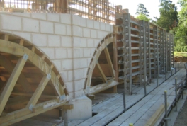
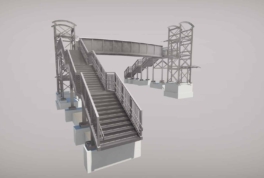
Raking, flying and dead shores are all types of shoring solution designed with temporary works equipment and again can be formed with either scaffold, soldiers or steels. Flying or horizontal shores are a system used to restrain party walls or front and rear walls, with beams spanning wall to wall. Its name comes from the fact that the equipment does not bear on the ground. Dead shores are used to provide vertical support to roofs, walls or floors.
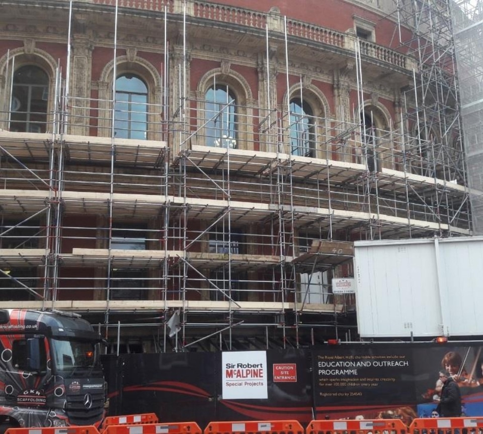
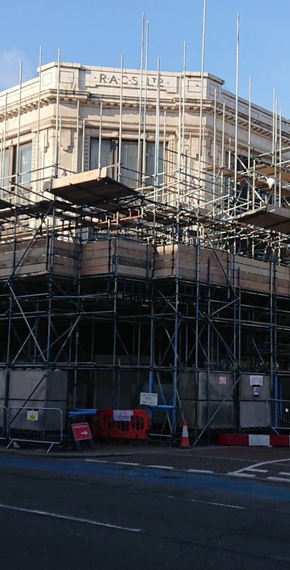
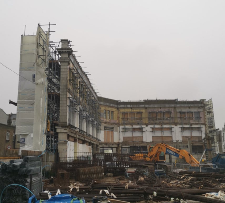
A façade retention structure provides lateral support to the existing façade of a building. These structures are typically required when restoring listed buildings, improving the internal structure of a building, or rectifying the stability of a façade which has been compromised. The restraint structure is generally required from the start of the demolition work until the completion of the new structure and should always be adequately co-ordinated within the design process to minimise impact with the proposed works. It is easy to achieve restraint prior to demolition but it can be problematic later if it clashes with and prevents the proposed works.
Investigating the Structure
It is crucial to thoroughly investigate the existing structure to identify all its defects, local weak points and loadbearing components. This is even more important with listed buildings which can be in poor condition due to their long exposure to the elements. For example, steel rebar can be corroded, bricks eroded, mortar washed out and timbers rotten.
Understanding the Proposed
Works and Sequencing
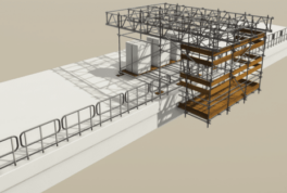
Façade restraints can be internal or external. Internal systems are often more efficient in terms of equipment as braced frames between walls can often be adopted. Whilst internal systems are often cheaper, they can be prohibitive and clash with proposed works and restrict access. External systems are often raking systems down to ground which typically take up more space and may require consents or licences for the land around the perimeter of the building.
Fixing to the Structure
Each solution to a façade restraint requirement is different, however good practice is to attempt to replicate the original restraint pattern of the façade, e.g. replace like-with-like at lateral support points. If site conditions allow, ties should be fixed through the window openings to avoid drilling into or through the masonry. Timber scaffold boards, packers or plastic caps are typically used to prevent scratches or damage to the building from the restraint structure.
Design Considerations
CIRIA C579 lists contributory factors in failures of retained façades, some of which are directly related to the design of façade retention structures.
- Lack of appreciation of the technical issues – HSE Guidance Note GS 51 states that the design of any façade retention system will be carried out by a chartered civil or structural engineer who is experienced in and understands the type of work being undertaken.
- Inadequate investigation of the existing construction – Site visits are vital to better understand the building. A list of information required to be obtained is provided in CIRIA C579 clause 5.7.
- Tying the structure to a façade for support – Consider the adequacy of connections between the façade and the retention structure. It is also important to consider the possibility of local failure of the fabric between the ties.
Detailed design considerations and loads applied are specified below:
- Demolition sequence; phasing to be established to provide stability of the structure
- The structure needs to resist wind loads; consider the wall to be solid (worst case) (see BS EN 1991-1-4 clause 7.4.1 (freestanding walls) or clause 7.2.2 (vertical walls of rectangular plan buildings))
- Any additional dead loads permanently or temporarily applied to the façade
- Additional horizontal load due to imperfections and offsets
- Accidental impact loads (See CIRIA C579 clause 8.5)
- Earth pressure and surcharge loading
Factors of safety on overturning (1.5) and sliding (2.0) - Assumed ground-bearing pressures; weak soil under the kentledge can cause the retention structure to tilt and damage the façade
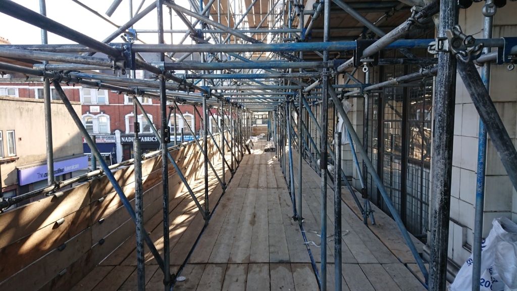
- Access requirements to the façade for repair works
- Joints in members/uprights or bracing; all joints in tension members should be spliced or mechanically bolted to resist tensile forces (good practice is to splice all joints to omit mistakes)
- Site conditions and limited space on-site can change the design significantly e.g. increasing the buttress width can reduce kentledge required
- Limiting the deflection will preserve the integrity of the retained structure. Low deflection limits on deflection results in very expensive and stiff restraint structures. CIRIA guidance recommends a limit for lateral deflection as H/750. Additional recommendations apply as per clause CIRIA8.10.1
- Design for foundation pads if ground conditions are not sufficient
Proprietary vs. Structural Steel
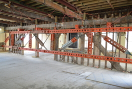
Proprietary systems such as RMD and Mabey are modular systems which can be manhandled and are therefore quick to install and later adapt. However, unless owned they can be very expensive to hire.
Structural steel is more expensive to design, install and adapt later. Connections and fabrication drawings must be prepared at the design stage, and members are often designed longer to minimise connections, making them difficult to manoeuvre and install. Dimensions need to be precise by undertaking a survey at the design stage, and often there is a requirement for site cutting and welding. In addition, the steel must be procured at the project outset, (which could be scrapped later), however the advantage is no hire costs are incurred during this time. In our experience the switchover point between proprietary kit and structural steel is typically 6 months.
On some projects where there is a requirement for an external access scaffold there are sometimes novel solutions to be achieved through a combined system of scaffold and shoring equipment, but again these are subject to a more detailed design approach.
Roles & Responsibilities
CIRIA C579 stresses that there must be “ownership” of the scheme at all stages from inception to completion of the whole of the works. An early appointment is recommended for façade retention work and for a suitably qualified and experienced temporary works co-ordinator (TWC). All parties must be aware of their responsibilities under CDM Regulations 2015.
Summary
With regards to façade retention scaffolds, these must be rigid structures and therefore the rules for typical independent T&F scaffold don’t apply. Some additional material (i.e. transoms, ledgers, standards and bracing) will be required, and in many cases mass foundations, concrete blocks or kentledge will also be required for stability. Often putting these within the scaffold structure can cause the scaffold to fail at the design stage under the weight of the kentledge alone. It may therefore be necessary to opt instead for either a modular soldier system or structural steels to form the restraint structure.
The reader is advised to refer to the CIRIA C579 guidance for further information.
References
CIRIA (2003) Retention of Masonry Façades – Best Practice Guide. CIRIA C579, London, Construction Industry Research and Information Association.